
Complex stimulation apparatuses "Plast-S"
Complex stimulation apparatuses of the "Plast-S" series combine traditional perforation with shaped charges and thermobarochemical treatment with the combustion products of gas-generating charges.
scroll down
 -
Promperforator
-
Equipment and technologies for well stimulation
-
Complex stimulation apparatuses "Plast-S"
-
Promperforator
-
Equipment and technologies for well stimulation
-
Complex stimulation apparatuses "Plast-S"

Complex stimulation apparatuses "Plast-S"
Complex stimulation apparatuses (hereinafter - CSA) of the "Plast-S" series are designed for shaped-charge perforation and two-stage local fracturing of a productive formation in a single trip on wireline or tubing (CT), in all casing sizes, in vertical, directional, and horizontal wells. CSAs are developed on the design basis of the Scorpion series perforators, which allowed retaining all the advantages of this perforator series in the apparatus. CSA is effective both as an independent tool for production enhancement and when used prior to hydraulic fracturing (frac) (to reduce the breakdown pressure). The treatment design is calculated using the multifunctional software "Plast", based on information from a questionnaire filled out by the Customer.
Operating principle:
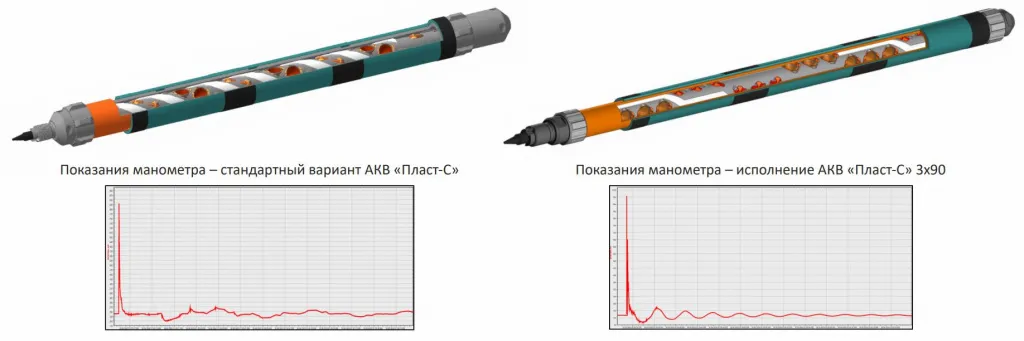
Upon initiation of the shaped charges, the internal gas-generating tapes (LGD) located inside the apparatus carrier ignite, creating local pressure, generating microfractures, and weakening the rock along the entire surface of the perforation tunnel. From the shaped-charge jets, as they exit the apparatus carrier, the external gas-generating propellants (ShNGD-PP) located on the outer surface of the apparatus carrier ignite. They create the primary fracturing pressure, leading to the formation of extended fractures. The residual deformation of the rock prevents the fractures from closing after the pressure dissipates. As a result, the well productivity is significantly increased. In the special modification of CSA "Plast-S" 3x90, shaped charges are arranged in groups of 3 per row with a 90-degree phasing. Upon firing, the shock waves from each charge in the group overlap, resulting in the formation of an additional fracture network between the perforated tunnels in the group, which significantly increases fluid conductivity, yielding an enhanced effect during complex stimulation compared to the standard charge arrangement. A specific feature of this modification is the reduced perforation density – 18 shots/m.
Safety
To reduce peak axial loads when operating the CSA on wireline, a shock-absorbing cable head NKPU.PP-65 is used, and when operating on tubing – a vertical shock absorber AT-73PP or AT-102PP. The process is monitored using an autonomous high-speed pressure memory gauge or a crusher gauge. Operational data from the pressure gauge allows adjusting the composition, arrangement, and mass of the explosive materials (EM) directly at the wellsite.
Distinctive features
Operating principle:
Upon initiation of the shaped charges, the internal gas-generating tapes (LGD) located inside the apparatus carrier ignite, creating local pressure, generating microfractures, and weakening the rock along the entire surface of the perforation tunnel. From the shaped-charge jets, as they exit the apparatus carrier, the external gas-generating propellants (ShNGD-PP) located on the outer surface of the apparatus carrier ignite. They create the primary fracturing pressure, leading to the formation of extended fractures. The residual deformation of the rock prevents the fractures from closing after the pressure dissipates. As a result, the well productivity is significantly increased. In the special modification of CSA "Plast-S" 3x90, shaped charges are arranged in groups of 3 per row with a 90-degree phasing. Upon firing, the shock waves from each charge in the group overlap, resulting in the formation of an additional fracture network between the perforated tunnels in the group, which significantly increases fluid conductivity, yielding an enhanced effect during complex stimulation compared to the standard charge arrangement. A specific feature of this modification is the reduced perforation density – 18 shots/m.
Safety
To reduce peak axial loads when operating the CSA on wireline, a shock-absorbing cable head NKPU.PP-65 is used, and when operating on tubing – a vertical shock absorber AT-73PP or AT-102PP. The process is monitored using an autonomous high-speed pressure memory gauge or a crusher gauge. Operational data from the pressure gauge allows adjusting the composition, arrangement, and mass of the explosive materials (EM) directly at the wellsite.
Distinctive features
- Versatility of design: The CSA is designed taking into account all the advantages of the Scorpion® series perforator design. The design is protected by RF patent No. 2637267;
- The special modification of CSA "Plast-S" 3x90 increases the treatment efficiency. The design is protected by RF patent No. 2844447;
- Complex stimulation: perforation + two pressure impulses acting on the productive formation, exceeding the formation pressure, with mechanical, physicochemical, and thermal effects on the rock;
- The use of the multifunctional software "Plast" allows preparing a preliminary treatment design, calculating the bottomhole assembly and the pressure generated by the apparatus;
- The apparatus can be used for pre-treatment before hydraulic fracturing, significantly reducing the initial proppant injection pressure and avoiding screenouts.
Technical Specifications of the "Plast-S" Series Apparatuses
| Parameter | Value | |||
|---|---|---|---|---|
| CSA "Plast-88S" | CSA "Plast-102S" | CSA "Plast-113S" | CSA "Plast-131S" | |
| CSA outer diameter / minimum casing drift diameter, mm | 79/88 | 102/112 | 113/123 | 131/141 |
| Maximum allowable operating temperature, when held for 2 hours, °C | 150 | |||
| Maximum allowable hydrostatic pressure, MPa | 80-140* | |||
| Minimum allowable hydrostatic pressure, MPa | 5 | |||
| Gas-generating charges used: | ||||
| internal | LGD | |||
| external | ShNGD-64PP | ShNGD-73PP | ShNGD-89PP | ShNGD-89PP |
| Mass of gas-generating charges, g: | ||||
| internal | 100±5 | |||
| external | 780±100 | 1600±100 | 1540±100 | 2100±100 |
| Specific volume of combustion gas products from internal/external charges, not less than, l | 70/546 | 70/1141 | 70/1008 | 70/1526 |
| Phase orientation of shaped charges, degrees - standard CSA design; - "3x90" design |
60 3x90 |
|||
| Section length, m | 1/2/3 | |||
| * The maximum allowable pressure may vary depending on the mechanical properties of the carrier tubes. | ||||
Specifications of the Shaped Charges Used
| CSA name | Shaped charge name | Charge type | Total explosive mass in the charge, g1) | Perforation density, shots/m |
Average parameters of charge penetration performance into a QC-type composite target, mm | ||
|---|---|---|---|---|---|---|---|
| Standard CSA design | "3x90" design | Penetration depth | Entrance hole diameter | ||||
| Plast-88S | Scorpion PP-15DP | DP | 13.3-15.8 | 20 |
18 | 700 | 8.5 |
| Scorpion PP-15BH | BH | 350 | 15.5 | ||||
| Plast-102S | Scorpion PP-20DP | DP | 14.3-16.8 | 750 | 11 | ||
| Scorpion PP-20SDP | SDP | 950 | 10 | ||||
| Scorpion PP-20BH | BH | 17.3-19.8 | 380 | 17.5 | |||
| Scorpion PP-20SBH | SBH | 18.3-20.8 | 210 | 21.5 | |||
| Plast-113S | Scorpion PP-25DP | DP | 25.3-27.8 |
16 | 1000 | 11 | |
| Scorpion PP-25SDP | SDP | 1200 | 10 | ||||
| Scorpion PP-25BH | BH | 600 | 20 | ||||
| Scorpion PP-25SBH | SBH | 24.3-26.8 | 250 | 23 | |||
| Scorpion PP-25OP | OP | 25.3-27.8 | 600 | 16 | |||
| Plast-131S | Scorpion PP-32DP | DP | 25.3-31.8 | 1100 | 11 | ||
| Scorpion PP-32SDP | SDP | 29.3-31.8 | 1300 | 10 | |||
| Scorpion PP-32OP | OP | 31.3-33.8 | 700 | 17 | |||
| Scorpion PP-32SBH | SBH | 24.3-26.8 | 210 | 25 | |||
| Scorpion PP-36SDP | SDP | 37.3-41.3 | 16 | - | 1600 | 12 | |
| Scorpion PP-36OP | OP | 35.3-37.8 | 1000 | 15 | |||
|
1) Depending on the explosive material used in the charge. |
|||||||
CONTACT US
We are always available and ready to answer your questions
Submit a request
Fill out the form and we will contact you within one business day